ANSI B212.18-2002 Designation
Boring Bars
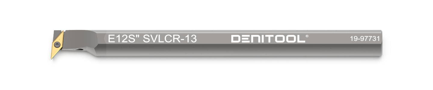
The above code example describes a right-hand side, internally cooled carbide boring bar with a shank diameter of 3/4", a functional length of ~10" (250mm, long version), and a tool angle of 95°. The insert is held with a screw. It has an indexable insert with 35° corner angles, 7° clearance angle and ~13mm (0.5") cutting edge length.
This boring bar is part of our Copy 35 ° turning program.
Designation symbols
1. | Type of bar
| Key | Material | coolant hole |
|---|---|---|
| E | Carbide | w/ |
| C | Carbide | w/o |
| A | Steel | w/ |
| S | Steel | w/o |
2. | Bar diameter
| Key | Shank diameter | Neck diameter |
|---|---|---|
| 0605 | 5/16" | 6 mm |
| 0806 | 6/16" | 8 mm |
| 1008 | 8/16" | 10 mm |
| 1210 | 10/16" | 12 mm |
| 05 | 5/16" | - |
| 06 | 6/16" | - |
| 08 | 8/16" | - |
| 10 | 10/16" | - |
| 12 | 12/16" | - |
| 16 | 16/16" | - |
| 20 | 20/16" | - |
3. | Bar length
| Key | Length |
|---|---|
| F | 80 |
| H | 100 |
| J | 110 |
| K | 125 |
| M | 150 |
| Q | 180 |
| R | 200 |
| S | 250 |
| T | 300 |
4. | Method of holding
| Key | Method |
|---|---|
| S | With screw through hole |
5. | Insert Shape
| Key | Included Angle | Shape |
|---|---|---|
| C | 80° | Diamond |
| D | 55° | Diamond |
| E | 75° | Diamond |
| G | 45° | Diamond |
| S | 90° | Square |
| T | 60° | Triangle |
| V | 35° | Diamond |
| W | 80° | Trigon |
6. | Bar geometry (lead angle)
| Key | Tool cutting edge angle | Insert shape |
|---|---|---|
| L | 95° | All |
| M | 40° | All |
| O | 5° | All |
| U | 93° | All |
| V | 15° | All |
| Q | 107.5° | D |
| Q | 95°, backwards | V |
| X | 50°, backwards | C |
| X | 93°, backwards | D |
| X | 113° | V |
7. | Insert clearance angle
| Key | Clearance angle |
|---|---|
| C | 7° |
| P | 11° |
| D | 15° |
8. | Hand of boring bar
| Key | Hand of boring bar |
|---|---|
| R | Right |
| N | Neutral |
| L | Left |
9. | Insert size
| Key | Insert size (mm) | Inscribed circle |
|---|---|---|
| 04 | 04 | 5/32" |
| 05 | 05 | 7/32" |
| 06 | 06 | 1/4" |
| 07 | 07 | 1/4" |
| 09 | 09 | 3/8" |
| 11 | 11 | 3/8" |
| 13 | 13 | 5/16" |
| 16 | 16 | 1/2" |